
How to Size a Drum FilterFlow, Solids Load and Mesh
Work out the right drum filter size from your flow rate, daily feed, mesh choice and installation space, with a short worked example.
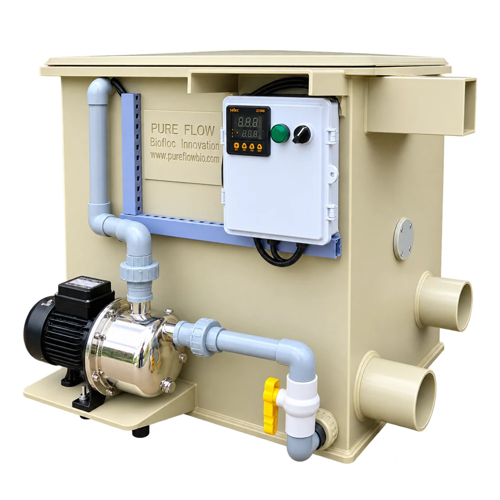 EQUIPMENT REFERENCE
See the mechanism.
Understand the duty.
Select a route or a stage to inspect the process. The cutaway explains the equipment and water environment; it is a teaching illustration, not a project drawing.
Capture solids
Use actual flow, screen opening and solids duty.
Particles are retained as water crosses the screen. Dissolved contaminants require other treatment stages.
- Use actual flow, screen opening and solids duty.
- Confirm approved levels, wash supply and waste drainage.
- Observe a complete guarded cycle before changing settings.
Key takeaways
- Start with flow: Add up the water that will actually pass the filter, in m³/h.
- Then the solids: In a fish farm the solids come from feed.
- Choose the mesh: A finer mesh clogs sooner, so a fine mesh effectively lowers the flow a given drum can handle.
- Leave headroom: Peaks happen: a feeding bout, a pump surge, a tank flush.
Start with flow
Add up the water that will actually pass the filter, in m³/h. For a fish tank, use the turnover you plan for. If you are unsure, the turnover rate guide shows how to get there.

Then the solids
In a fish farm the solids come from feed. As a rough guide, a quarter to a third of the feed you add ends up as solids, depending on the feed and species. More feed means a heavier load, and a heavier load means the filter washes more often. If the filter is only just big enough, it will wash non-stop.
Work with your own numbers.
Use the tools below to explore the relevant arithmetic. Enter measured values or declared assumptions. An estimate does not establish equipment capacity, biological performance or a safe operating limit.
Flow & turnover planner
Relate a measured water volume to a selected turnover time. Confirm the time from the application and hydraulic design.
Assumptions and limits
A planning allowance is your assumption. This calculation does not choose a filter, prove treatment capacity or account for pump head.
Measured wash-water use
Use measurements across complete wash cycles and the recorded daily cycle count.
Assumptions and limits
Identify whether you measured wash supply or total waste discharge. No default litres per Pureflow wash cycle are assumed.
Convert units before you calculate
Planning arithmetic · inputs remain visible for review · example values are not operating recommendations
Choose the mesh
A finer mesh clogs sooner, so a fine mesh effectively lowers the flow a given drum can handle. Pick the mesh first, then check the flow rating at that mesh. See mesh size.
Leave headroom
Peaks happen: a feeding bout, a pump surge, a tank flush. Choose a model rated comfortably above your normal flow, so peaks do not make the water spill over the top.
Check the room
You need space for the filter, its drain, service access and often a collection tank for sludge. Measure the head available between tank outlet and filter inlet if you want gravity feeding.
A quick example
A recirculating tank loop of 30 m³/h with a fine mesh and heavy feeding might call for a filter rated well above 30 m³/h, not exactly at it. Bring us your numbers and we will check them against our RDF range.
Pureflow Bio equipment for this
Standard drum filters (RDF) →Automatic solids removal.Pro drum filters →Compact pump-fed drum filters.Confirm the hydraulic duty
Use these questions to prepare a project brief or an operating review. Check an item only when the information has been recorded for your installation.
This checklist is a working aid in the current page session, not a saved maintenance record.
How to Size a Drum Filter FAQ
Can I size a drum filter from tank volume?
Not reliably. Flow, feed and mesh are better inputs than volume.
What if I am between two sizes?
Go up. A slightly larger filter washes less often and copes with peaks.
More guides related to how to size a drum filter
Discuss your system with Pureflow.
Share your application, operating volume, actual flow, loading and the question you are trying to resolve.