
Sump and Pump Station DesignWhere the Clean Water Goes
How to design the sump or pump station after a gravity-fed filter: volume, level control and pump protection.
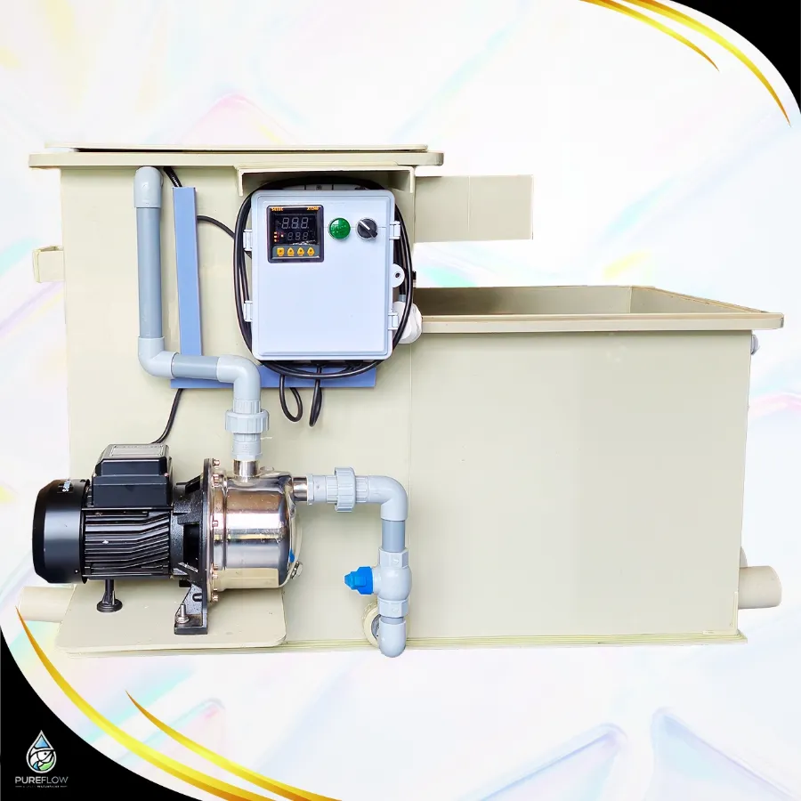 EQUIPMENT REFERENCE
See the mechanism.
Understand the duty.
Select a route or a stage to inspect the process. The cutaway explains the equipment and water environment; it is a teaching illustration, not a project drawing.
Supply the pump
Check the complete pump and system duty.
Maintain the approved suction arrangement and avoid dry running or air ingress.
- Check the complete pump and system duty.
- Use internal pipe dimensions and measured operating flow.
- Review supply conditions, protection and service isolation.
Key takeaways
- Why a sump: It decouples the filter from the pumps, holds a working volume and gives you one place to add heaters, skimmers or dosing.
- Size: Large enough that the pump does not start and stop too often, and that power loss does not flood the sump.
- Level control: Fit float switches or sensors for low-level pump protection and a high-level alarm.
- Pump protection: Keep the pump inlet well submerged and away from air-entraining flows.
Why a sump
It decouples the filter from the pumps, holds a working volume and gives you one place to add heaters, skimmers or dosing.

Size
Large enough that the pump does not start and stop too often, and that power loss does not flood the sump. Allow for the water that drains back when pumps stop.
Work with your own numbers.
Use the tools below to explore the relevant arithmetic. Enter measured values or declared assumptions. An estimate does not establish equipment capacity, biological performance or a safe operating limit.
Pump or equipment energy cost
Estimate electrical use from measured input power and a declared daily operating schedule.
Assumptions and limits
Use electrical input, not hydraulic power or the pump’s flow rating. Starting load, variable duty, taxes and demand charges are not included.
Pipe-loss planning scenario
Estimate pipe friction and local losses from explicit hydraulic assumptions.
Assumptions and limits
The Darcy factor and K values must suit your pipe and fittings. Excludes unlisted equipment losses, fouling, transients and pump-curve verification. Do not use as an installation approval.
Convert units before you calculate
Planning arithmetic · inputs remain visible for review · example values are not operating recommendations
Level control
Fit float switches or sensors for low-level pump protection and a high-level alarm. Add a top-up arrangement if evaporation matters.
Pump protection
Keep the pump inlet well submerged and away from air-entraining flows. See choosing a pump.
Access
Leave room to service pumps and clean the sump.
Pureflow Bio equipment for this
Standard drum filters (RDF) →Automatic solids removal.Pro drum filters →Compact pump-fed drum filters.Coordinate the levels and losses
Use these questions to prepare a project brief or an operating review. Check an item only when the information has been recorded for your installation.
This checklist is a working aid in the current page session, not a saved maintenance record.
Sump and Pump Station Design FAQ
How big should the sump be?
Big enough for drain-down volume plus a working buffer.
Can the sump hold the biofilter?
Often yes in small systems. Large systems keep them separate.
More guides related to sump and pump station design
Discuss your system with Pureflow.
Share your application, operating volume, actual flow, loading and the question you are trying to resolve.