Recirculating aquaculture systems.
Every stage, connected.
Follow the water from the culture tank to the return line. Explore the equipment, understand the treatment duties and build a clearer brief for your RAS project.
 RAS / SYSTEM CONCEPT
A fish farm is also
a water-treatment plant.
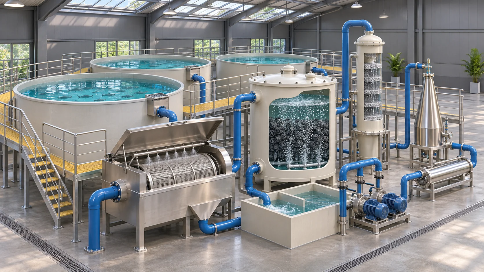
A recirculating aquaculture system treats and reuses culture water. Its success depends on how the stock, treatment equipment and operating team work together.
Water reuse changes the engineering question: what enters with the feed, and where does it leave the system?
Feed supports growth, but it also creates a treatment load. Suspended waste needs to be collected; dissolved nitrogen compounds need biological conversion; and the system must balance oxygen, carbon dioxide, temperature and water chemistry.
The equipment is therefore selected as a connected train. A large tank or a fast pump cannot compensate for an underperforming biological stage, poor gas transfer or an untested recovery plan.
Start with production.
Define species, production stage, peak biomass and maximum daily feed before fixing the treatment duty.
Follow every outlet.
Review the water, sludge, off-gas, discharge and heat routes alongside the main recirculating line.
Design for interruption.
Power, oxygen, water levels, alarms and trained operators belong in the project from the beginning.
See what each stage
actually does.
Follow the process routes, run a wash cycle and select a treatment stage. The cutaway shows equipment functions without presenting the layout as a project drawing.
Culture tanks
Collect waste before it settles.
The culture tank is both an animal environment and a hydraulic vessel. The return flow should distribute oxygenated water and move settleable waste toward the intended outlet. Tank shape, drain arrangement and the behaviour of the stock determine how well this happens.
- Confirm the operating water volume and peak feed.
- Check circulation, drain capture and access for inspection.
- Record oxygen at the animal zone, not only in the return pipe.
Water reuse brings
a different set of responsibilities.
Compare the operating approach before comparing equipment. There is no single water-saving percentage or energy figure that describes every farm.
Recirculating aquaculture
Water passes through a treatment train and returns to the stock.
Turn the feed plan
into a visible treatment scenario.
Explore hydraulic flow, nitrogen load, oxygen, solids and media volume together. The example is an arithmetic scenario: replace its assumptions with supported project values.
Review the calculation assumptions
Protein nitrogen is taken as protein ÷ 6.25. All release, demand, conversion, fill and water-change values are editable scenario assumptions. They are not verified Pureflow capacities or operating recommendations.
Show the formulas and units
Flow = operating volume ÷ selected turnover time. Feed nitrogen = feed × protein fraction ÷ 6.25. TAN-N = feed nitrogen × selected release fraction. Oxygen = feed × selected oxygen coefficient. CO₂ = oxygen × selected CO₂ coefficient. Dry solids = feed × selected solids fraction. Media volume = TAN-N in g/day ÷ selected conversion rate. Reactor volume = media volume ÷ fill fraction. Makeup water = operating volume × selected daily replacement fraction.
Make the measurements
mean the same thing.
A useful operating record includes the unit, sampling location and test basis. Establish the actual limits with the species programme and approved operating plan.
| Parameter | Record the basis | Read it alongside |
|---|---|---|
| Dissolved oxygen | mg O₂/L and, where relevant, % saturation | Measure at the stock and the critical treatment locations. Temperature, salinity, transfer and demand affect interpretation. |
| TAN and free ammonia | mg N/L; distinguish TAN-N from NH₃-N | Record pH, temperature, salinity and the analytical basis. A total-ammonia result does not directly equal unionised ammonia. |
| Nitrite | State NO₂-N or NO₂⁻ explicitly | Use the same reporting basis throughout the stock and treatment review. Species and water chemistry affect the response. |
| Carbon dioxide | mg CO₂/L; document the measurement method | Check degassing duty and ventilation. An oxygen reading alone does not establish the CO₂ condition. |
| pH and alkalinity | pH; mg/L as CaCO₃ for alkalinity | Track the biological process and source-water contribution. A buffer dose needs a measured balance and an operating procedure. |
| Nitrate | State NO₃-N or NO₃⁻ explicitly | Review accumulation, makeup water and any separate nitrate-removal duty. |
| Temperature | °C; include daily and seasonal variation | Use species- and life-stage-specific requirements. Assess heating, cooling and failure conditions. |
| Suspended solids | mg/L; record sampling and test method | Review particle characteristics, feed, capture and wash discharge. Visual clarity alone is not a complete solids measurement. |
| Salinity and ionic balance | ppt or a defined conductivity basis | Confirm the species programme, biofilter acclimation, materials and test interpretation. |
| UV transmittance | UVT at a stated wavelength and path length | Use this with actual reactor flow and validated performance. Lamp watts alone are insufficient. |
A universal “safe range” would conceal important species, salinity and life-stage differences. Review the water-quality guide ↗ or use the freshwater ammonia-fraction calculator ↗ with its stated input basis.
Choose the stock.
Then define the environment.
Species choice connects climate, water chemistry, seed supply, the production cycle and the market. Select a species to review the questions its system must answer.
The thermal strip shows a broad relative group, not a control setpoint or a safe operating limit. A species profile cannot establish an allowable stocking density.
Nile tilapia
Oreochromis niloticusA warm-water production choice where the local market, permitted stock and water supply fit the project. Evaluate the heating requirement alongside the feeding plan rather than choosing a system from tank volume alone.
Published culture context: 25–30 °C; confirm the strain and life stage.
An empty tank is
the right time to test the system.
Startup is a sequence of acceptance checks, not a promise that biology will be ready on a particular calendar date.
Prove the water route
Commission levels, drains, valves, pumps, flow measurement and leak control. Confirm that normal starts and stops do not create an unintended overflow or empty a critical vessel.
Prove the safeguards
Check alarm destinations, sensor checks, standby power and the independent stock-protection arrangement. Operators need a procedure they can use when the normal system is unavailable.
Establish the biology
Use a documented fishless or otherwise approved startup method. Keep the process within its intended water chemistry and temperature, and avoid transferring pathogens with unverified seed media.
Challenge and increase load
Measure the response to the planned loading step. TAN and nitrite trends, oxygen, pH and alkalinity support the next decision. Increase stock and feed gradually under the operating plan.
UF/IFAS discusses biofilter establishment and the importance of monitoring during startup. Follow the protocol appropriate to the stock and system. Read the primary extension guidance ↗
Ask what happens
when one part stops.
Select a scenario to see the chain of consequences and the operating question. This is a design review aid, not a remote fault diagnosis.
Power or pump loss
A generator is useful only when the whole recovery chain works: detection, starting, transfer, connected loads and a trained response. A single universal “safe outage time” is not a design basis.
Establish the responseProvide the approved independent oxygen response, alarm route and circulation recovery plan. Test the complete sequence under the site procedure.
Review backup power and alarms ↗Water savings have
an operating cost.
Compare the complete production plan: capital, seed, feed, energy, labour, maintenance, waste management and the route to market.
Review the loads that run every day.
Circulation, aeration, oxygen supply, temperature control and disinfection have different load profiles. Use measured electrical input or supplier data at the intended operating point. Do not estimate the whole farm from a pump’s nominal flow rating.
A lower pumping lift can reduce one load, while a colder source or a different building can change another. Record the boundaries when comparing energy per kilogram of fish: which equipment, which production stage and which period are included?
Checklist marks stay in this page session; they are not a saved operating record.
What does this load cost?
The initial values are an illustrative example. Enter the actual connected load and tariff.
Calculation basis
Energy = input kW × operating hours/day × 30 days. Cost = energy × rate. This simple estimate excludes demand charges, varying tariffs, power factor adjustments and other equipment loads.
Select the equipment
around the duty.
Start with the treatment objective and the installation conditions. Catalogue listings and model drawings support selection; the conceptual illustrations below do not establish capacity.
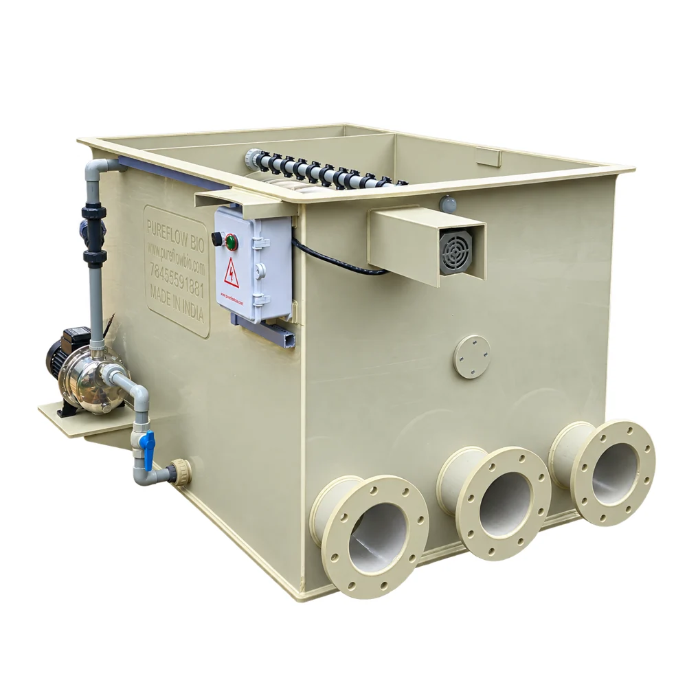
Standard drum filters
Separate retained particles and direct wash waste out of the circulating line. Review the model against flow, mesh and solids duty.
Explore this treatment stage ↗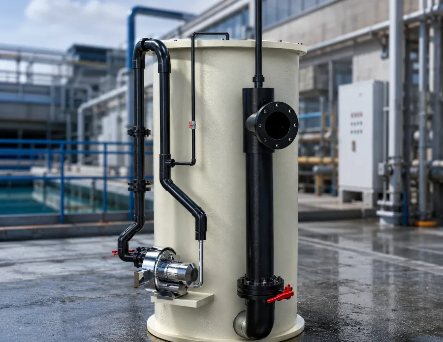
Moving bed biofilters
Review the media, aeration and reactor arrangement against the defined nitrogen load and operating conditions.
Explore this treatment stage ↗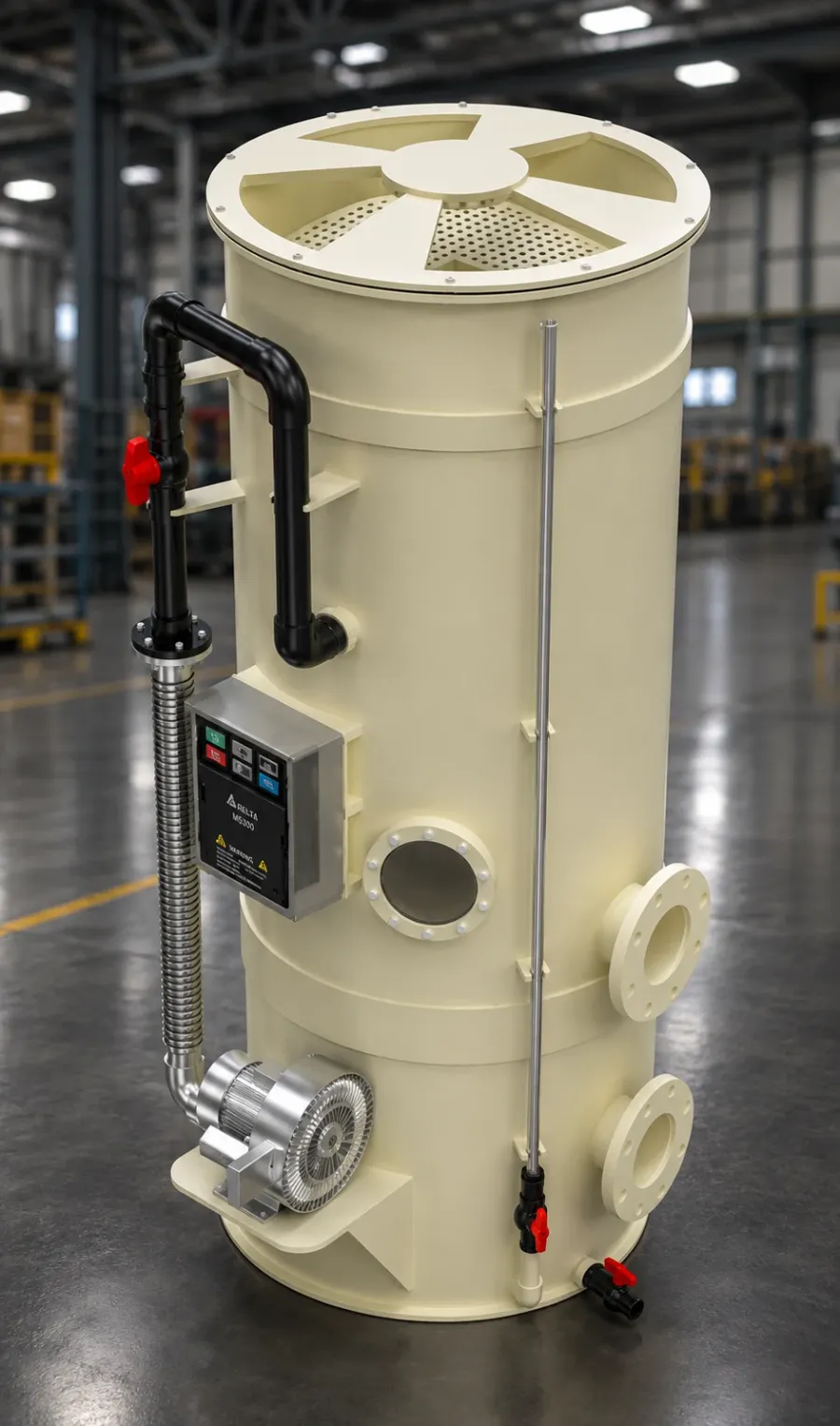
Degassing solutions
Coordinate water distribution, gas-transfer duty and ventilation as part of the complete treatment train.
Explore this treatment stage ↗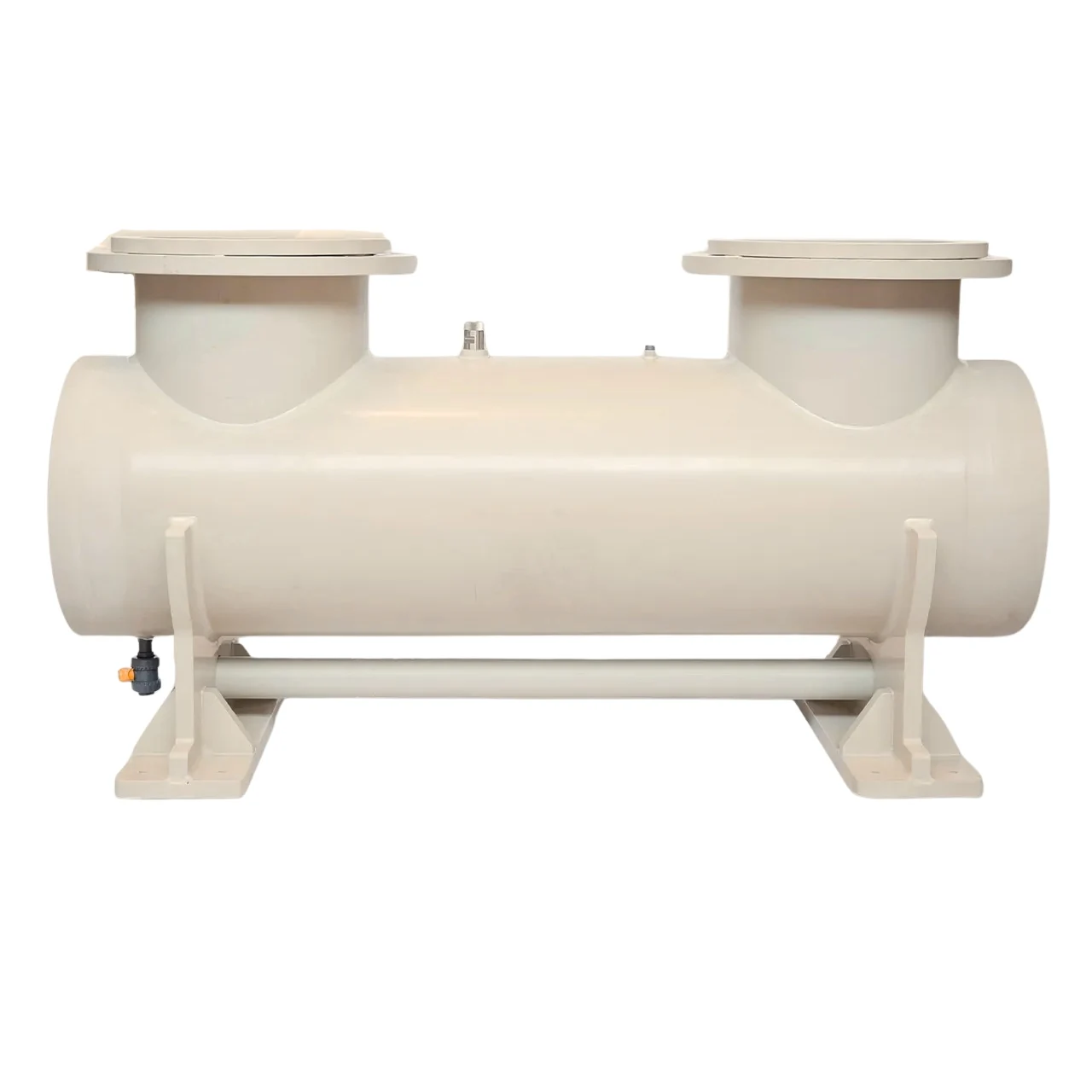
UV treatment systems
Specify the treatment objective, actual reactor flow and water conditions before reviewing validated performance.
Explore this treatment stage ↗Confirm the supplied configuration, materials, interfaces, dimensions and operating duty in the project quotation and approved documents. No model capacity or complete-farm performance is inferred from a render.
Questions to settle
before the build.
Direct answers for a project review, with the important assumptions kept visible.
Prepare your project brief ↗What is a recirculating aquaculture system?
A RAS is a tank-based culture system that treats and reuses water. The treatment train manages suspended solids, dissolved nitrogen compounds, gases and other application-specific water conditions before water returns to the stock.
Does a RAS eliminate water replacement?
No. Makeup water is still needed for losses and water-quality management. The amount depends on feed, treatment, salinity, nitrate control and the site water balance. Recirculating flow and daily makeup volume are different measurements.
Why is feed important when planning a RAS?
Feed connects the production plan with waste and oxygen demand. Peak daily feed helps define treatment loading, while tank volume and selected turnover time describe a separate hydraulic requirement. Both are needed.
Can the planner choose the right Pureflow model?
It provides a transparent scenario, not an automatic equipment certification. Pureflow model selection also needs approved catalogue data, screen and solids duty, water chemistry, installation levels and the project design conditions.
How much biofilter media is required?
Divide the defined TAN-N load by a conversion rate supported for the selected media and operating conditions. Reactor volume is then related to the specified media fill share. The example rate in the planner is an arithmetic assumption, not a Pureflow rating.
Does a drum filter replace a biofilter?
No. A drum screen separates retained suspended particles. A biofilter converts dissolved nitrogen compounds. Removing solids early can protect downstream treatment, but the two stages perform different jobs.
Why do oxygenation and degassing need separate attention?
Oxygenation supplies oxygen. Degassing transfers unwanted dissolved gas, including carbon dioxide, into a ventilating air stream. A system can have adequate oxygen delivery and still require better CO₂ removal.
Can lamp watts or residence time prove UV dose?
No. Use the reactor’s validated performance at the actual flow and water conditions, including UV transmittance. Lamp power and nominal hydraulic time do not establish the delivered dose or organism-specific reduction.
How should a new biofilter be commissioned?
Commission the hydraulic system and safeguards first, then establish and challenge the biological process under a documented startup protocol. Increase stock and feed only when the measured process response supports the next loading step.
What happens during a power failure?
The consequences depend on current loading and the available independent safeguards. The site needs a tested alarm, oxygen and circulation recovery plan. A generic number of minutes cannot establish a safe outage for every farm.
Is RAS always more economical than pond farming?
No. RAS can offer control and reduced water demand but brings capital, energy, skill and maintenance requirements. Compare the complete production cost, stock performance, market and risks for the intended location.
What information should I send Pureflow?
Send the species and production stage, operating water volume, peak daily feed, intended flow, source-water information, site conditions and the current project question. Approved drawings and the equipment duty can then be reviewed together.
Bring the operating question.
We’ll review the system.
Share the species, production stage, peak feed, water conditions and site constraints. A clear brief makes it easier to review the treatment train and the equipment interfaces.
Call +91 98444 11881 · WhatsApp +91 98455 91881
Equipment supply, installation and project scope are defined in the quotation.
Your working project brief.
Prepare a text summary locally. Nothing is sent automatically.